CVE-2025-67736 FreePBX Authenticated SQL Injection leads to RCE
Overview This will be fairly straight to the point since it’s another FreePBX vulnerability. It’s an authenticated SQLi, so not the end of the world as you’d...
Vulnerability hunting is hard, and it’s even harder if you don’t have access to the source. Hardware devices make this even tougher as usually the firmware is distributed via binary blobs. You can binwalk them and get a squashfs usually, but IMO it’s still not the same as seeing exactly what’s running dynamically on your router. So, lets hardware hack our way in using some built-in functionality :)
I did a talk titled Hardware Hacking: The Easy Way In… at The Pwn School Project hosted by Phillip Wylie on 17 FEB 2021 where I do a live demo of this entire process, from soldering to dropping into the root shell.
Beginning of live demo @ 29:47
I was inspired by Flashback Team: How We Hacked a TP-Link Router and Took Home $55,000 in Pwn2Own.
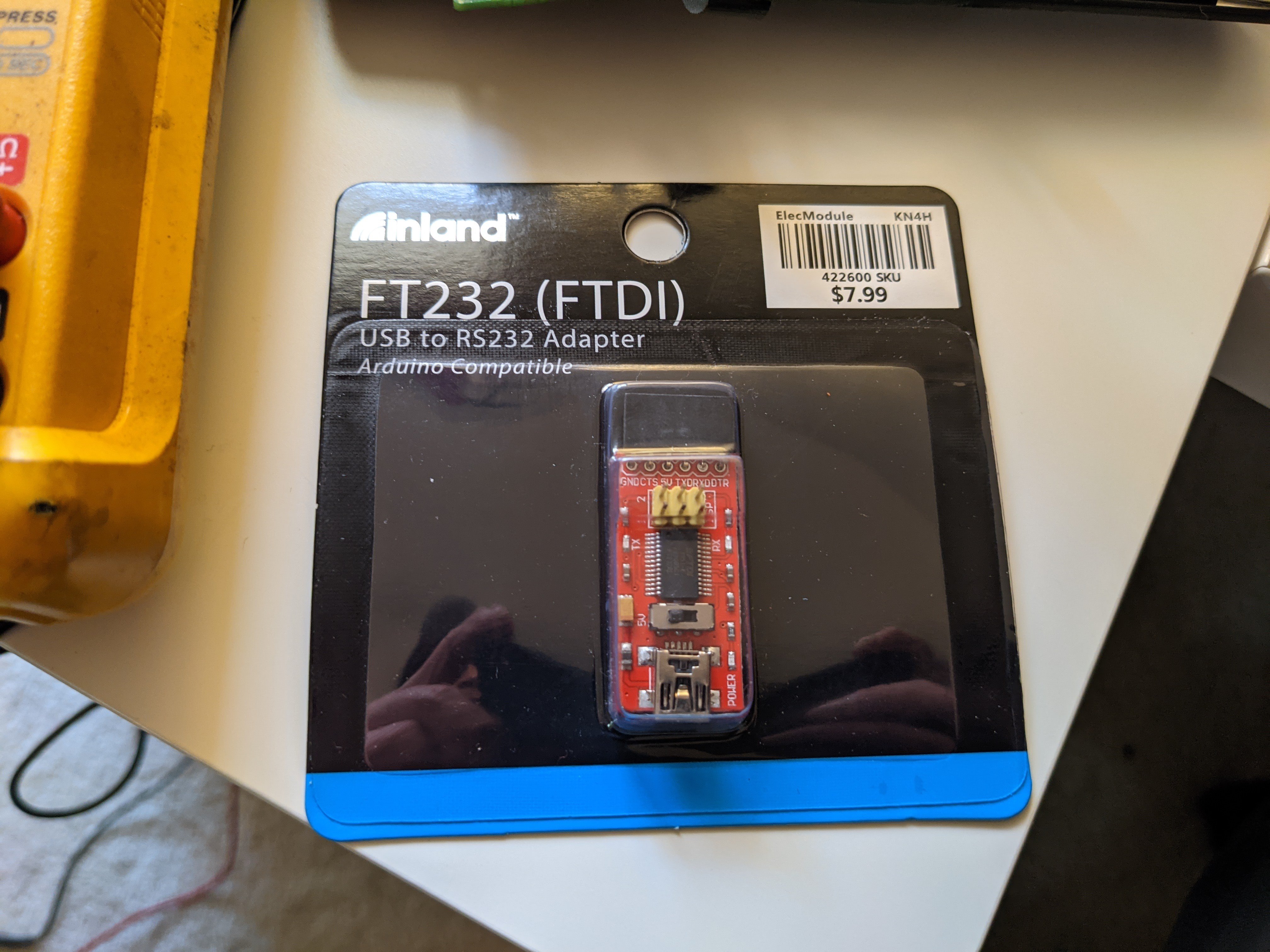
You will need:
The router you see in this how-to is a tp-link TL-WR841N but this technique can be used on many different boards. I’ve also done this successfully on a NETGEAR R6080
I am also using Ubuntu 20.04, but any Linux OS should work, or something like Putty on Windows.
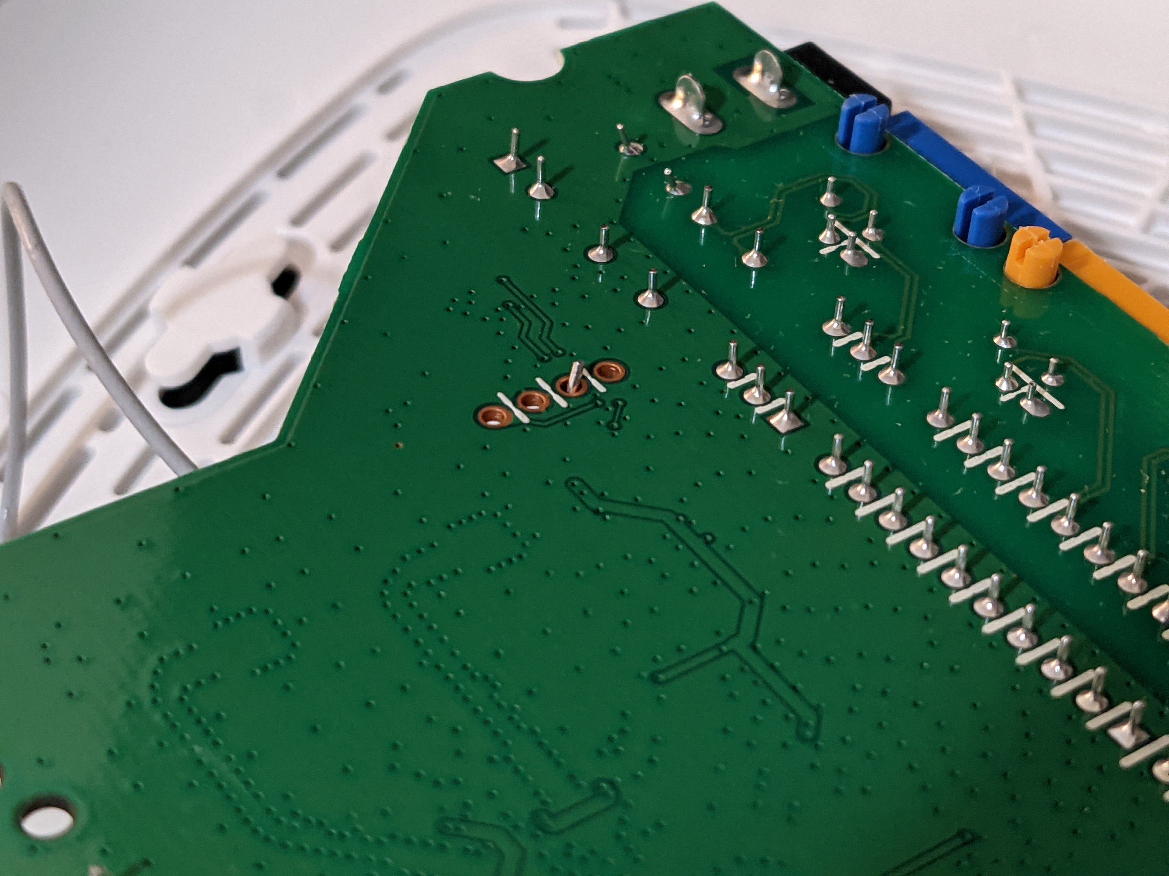
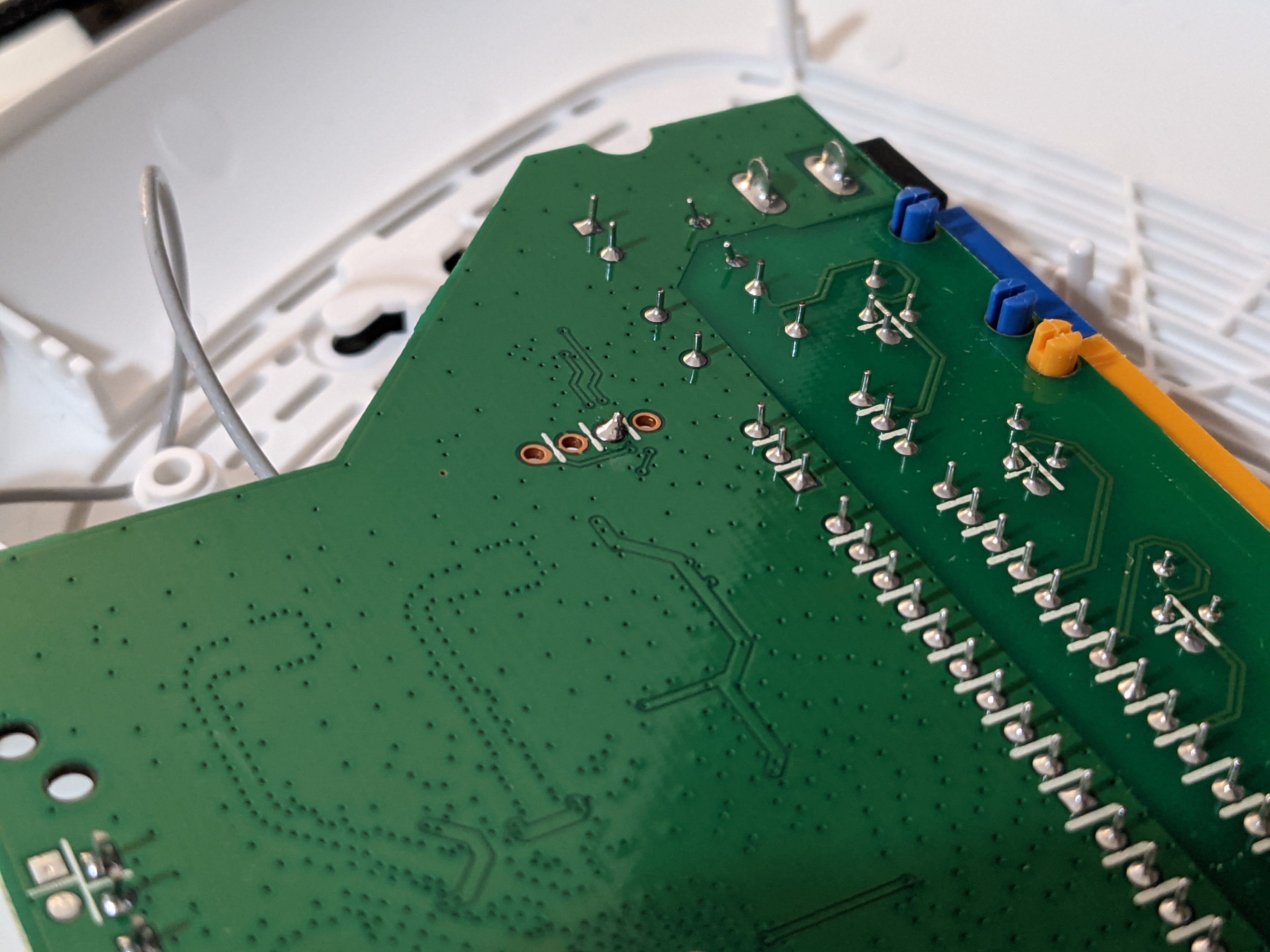
Start by taking your router apart and finding the UART port on the circuit board. It will look like this:
Luckily here, the ports are clearly labeled For this model
VCC - 3.3 volts DC constant
GND - Ground
RX - Receive data
TX - Transfer data
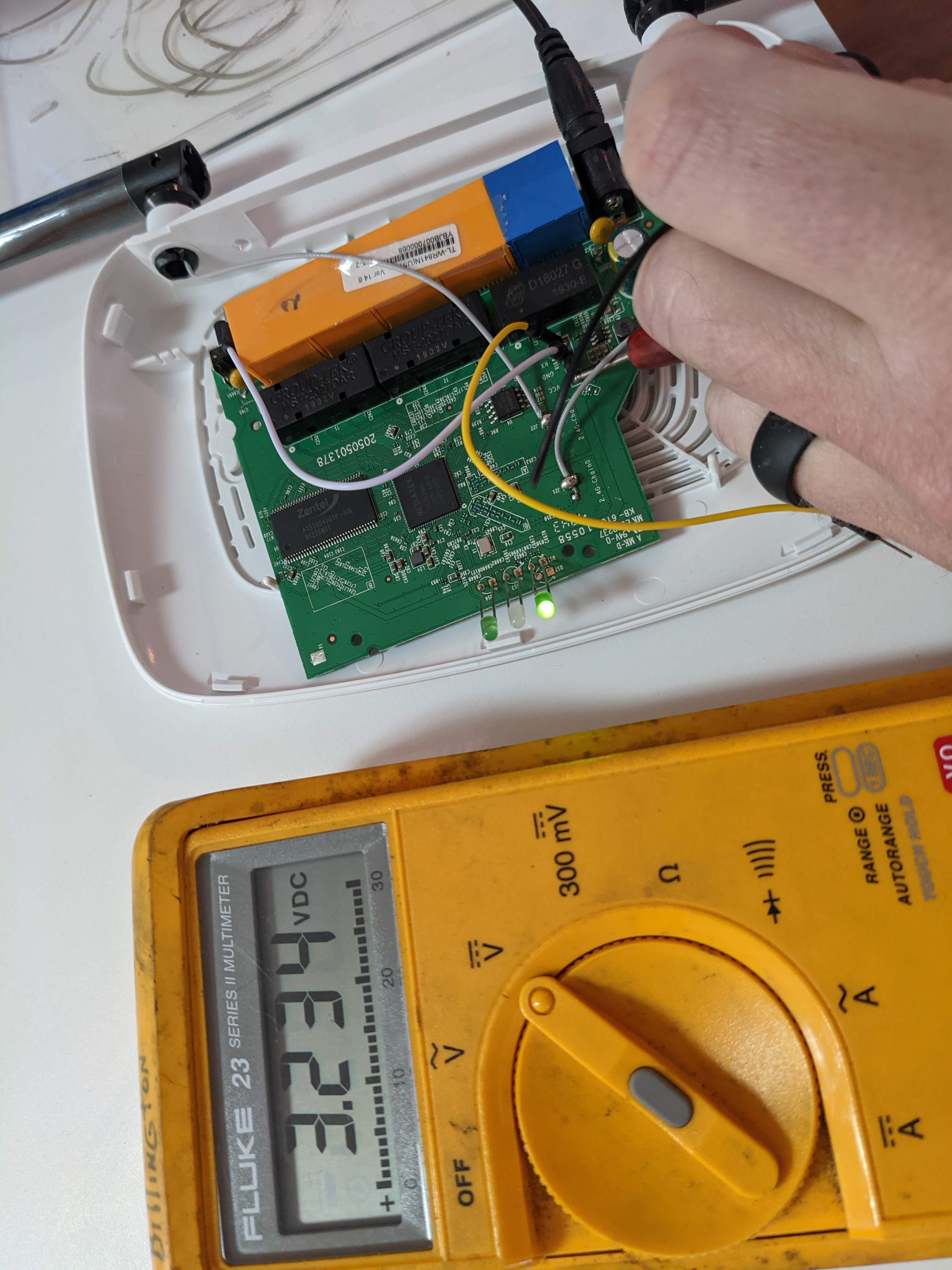
Now would be a good time to identify these if they weren’t labeled. Ground is pretty easy… Just measure resistance between each pin until you find 0 ohms. I use the diode checker as it gives an audible indication when you hit 0 ohms. I leave it for a couple seconds as RX can also give 0 for a split second. You want a constant 0.
TX can be a bit trickier. You will be looking for almost 3.3v. A solid, steady 3.3v is likely VCC, whereas TX is going to fluctuate a bit, as this voltage is actually data being sent. An analog multimeter might make identifying this a bit easier (thinking back to Simpson multimeters in my Navy days…) as you would be able to see the needle bounce a bit. Worst case here, trial and error between VCC and TX.
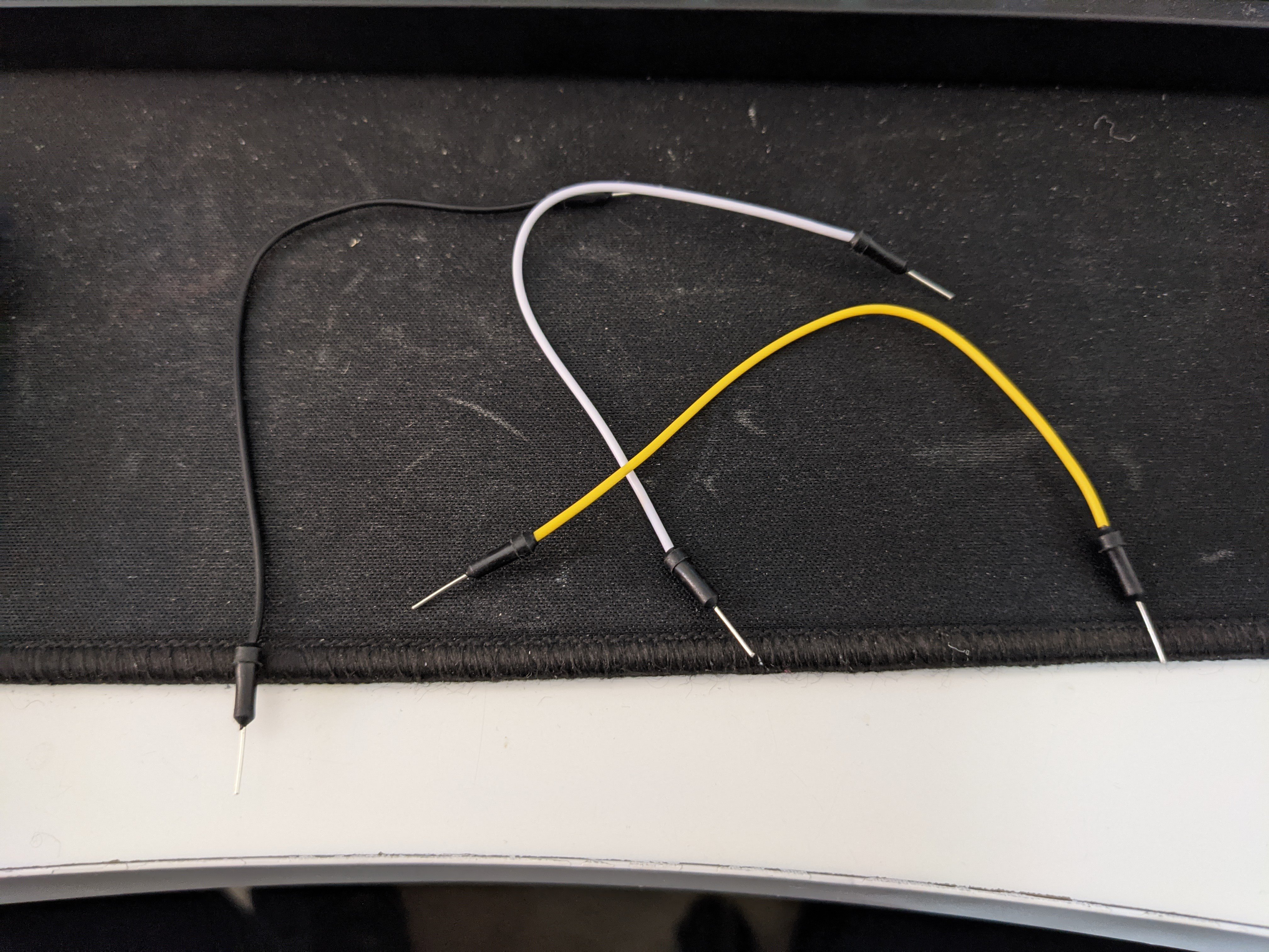
At this point, you are probably ready to start soldering if you want to do that. The process for me looked like this:
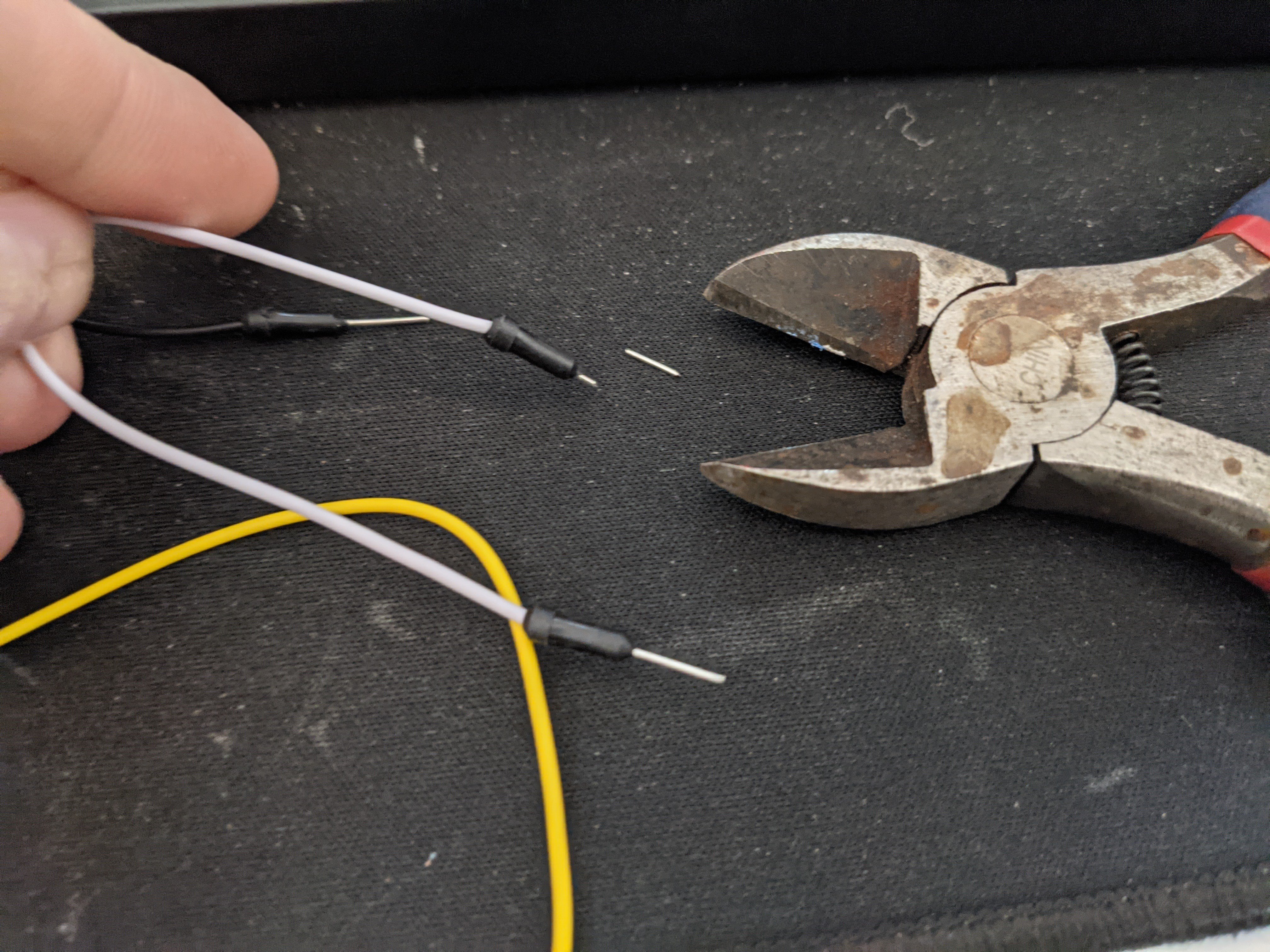
Repeat for each jumper TX RX GND
Now, you are ready to connect these jumpers to your FTDI controller. Here is a pic of the pinout from my setup:
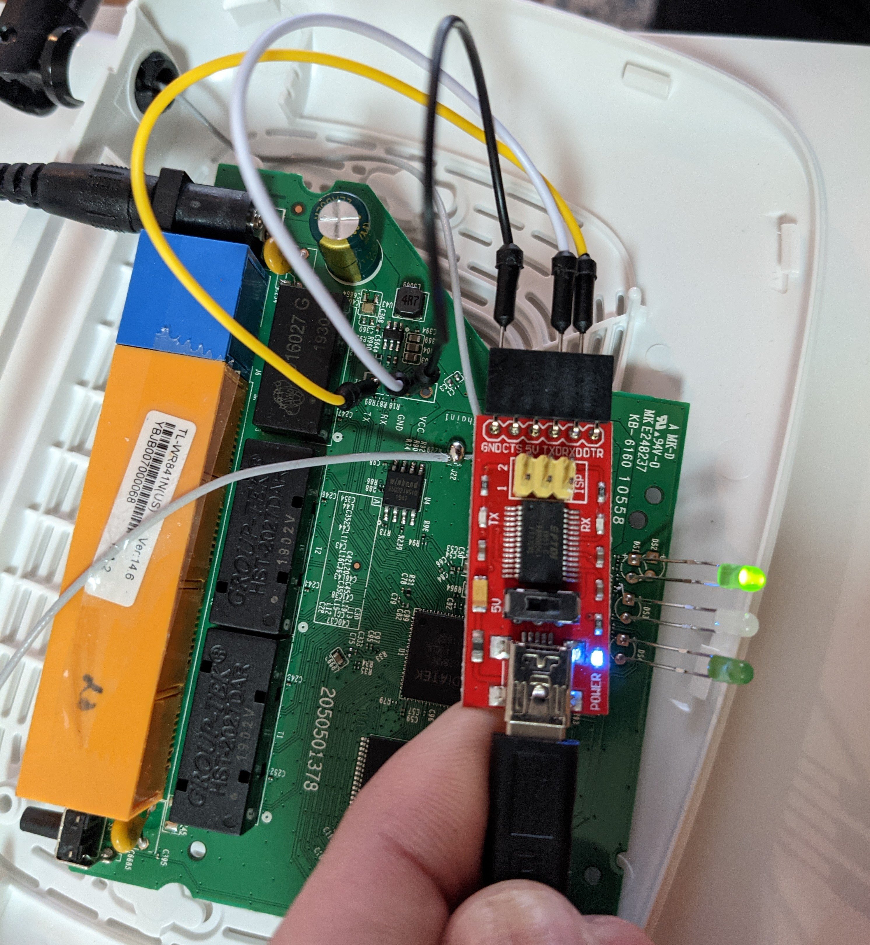
You can see, these will appear backwards. What is being transmitted (TX) from the router will be received(RXD) on the FTDI controller. If you mix these up, your router will probably just not boot, which is what mine just did when I tested this. In that case, just swap them and try again.
You’ll then want to confirm voltage and set your controller appropriately. Mine had a switch for 5v or 3.3v, so I set it to 3.3v. To check, measure voltage at the VCC port:
Now you are almost ready to boot the router. Connect your controller to your computer and look for the device file. It will probably be:
/dev/ttyUSB0
which you can find by running:
ls /dev/ttyU*
From here, you’ll need something to connect to that serial device. I used screen, which you can install using:
apt install screen
To connect to the serial device, you’ll run the following as root:
screen /dev/ttyUSB0 <baud rate>
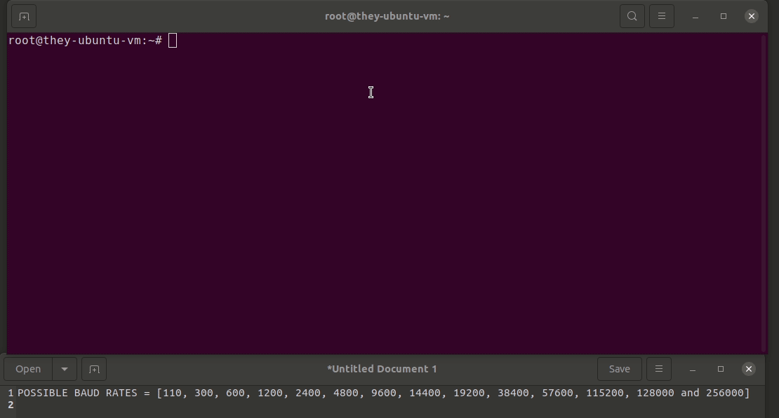
The possible baud rates are:
110 300 600 1200 2400 4800 9600 14400 19200 38400 57600 115200 128000 256000
In this case, the correct baud rate was 115200, so the command looked like this:
screen /dev/ttyUSB0 115200
After running the command, you will then power the router on. It will automatically start transmitting data and you will see output. If you get this incorrect, you’ll just get jibberish on the screen like so when you plug the router in.:
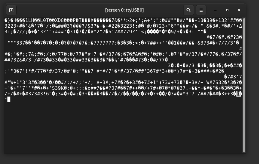
This is fine, just exit using Ctrl + a and then :quit and try again. When you get the baud rate correct, you will see a boot log output to the screen when you power the router on. It will look like this gif and you will drop into a shell:
After running the screen command in the gif above, I power the router on, which is the delay before the log is printed to screen. Also, you will likely not get a shell prompt, and messages will keep displaying to screen even after you have a shell. So, I recommend running something like ls to see if you get output. You can also see that this router does not have a lot of commands. Most of the functionality on this machine would come from /bin/busybox, which contains more functionality/commands. Sometimes, you may want to copy over a full busybox binary that has more built-in commands.
Overview This will be fairly straight to the point since it’s another FreePBX vulnerability. It’s an authenticated SQLi, so not the end of the world as you’d...
Overview When I was starting out in penetration testing, it always confused me how folks would say they worked using a simple CLI only linux machine in a VPS...
Overview I recently noticed quite a few folks recently looked at Nagios XI. Some even pulled the obfuscated stuff apart which I thought was really awesome! I...
CVE-2021-42840 This one will be a bit short, since severity/impact/video/etc is all identical to my post on the previous SuiteCRM RCE.
Path traversal in File Upload leads to Remote Code Execution in Chamilo LMS Overview It’s been a bit since I spent some time looking for a web vuln… And this...
tldr/oneliner ruby -e '"".class.ancestors[3].system("cat /etc/passwd")' Why? So I was doing a bit of reading on SSTI, specifically that of Jinja/python which...
Remediation testing I found another vulnerability during remediation testing, and that writeup can be found here.
TL;DR Just go to the Demo Or, just go to the Demo Round 2 for reverse tunneling Accessing Resources Behind Multiple Resources At some point, you may run into...
How to get a Shell on your Router (hopefully) Vulnerability hunting is hard, and it’s even harder if you don’t have access to the source. Hardware devices ma...